UC3843B ST Current Mode PWM Controller Data Sheet
Download PDF datasheet for STMicroelectronics / ST UC3843B High Performance Current Mode PWM Controller (EN) 15 pages 1999 zip
Description
This PDF data sheet is for the ST UC3843B PWM controller.
About the Item
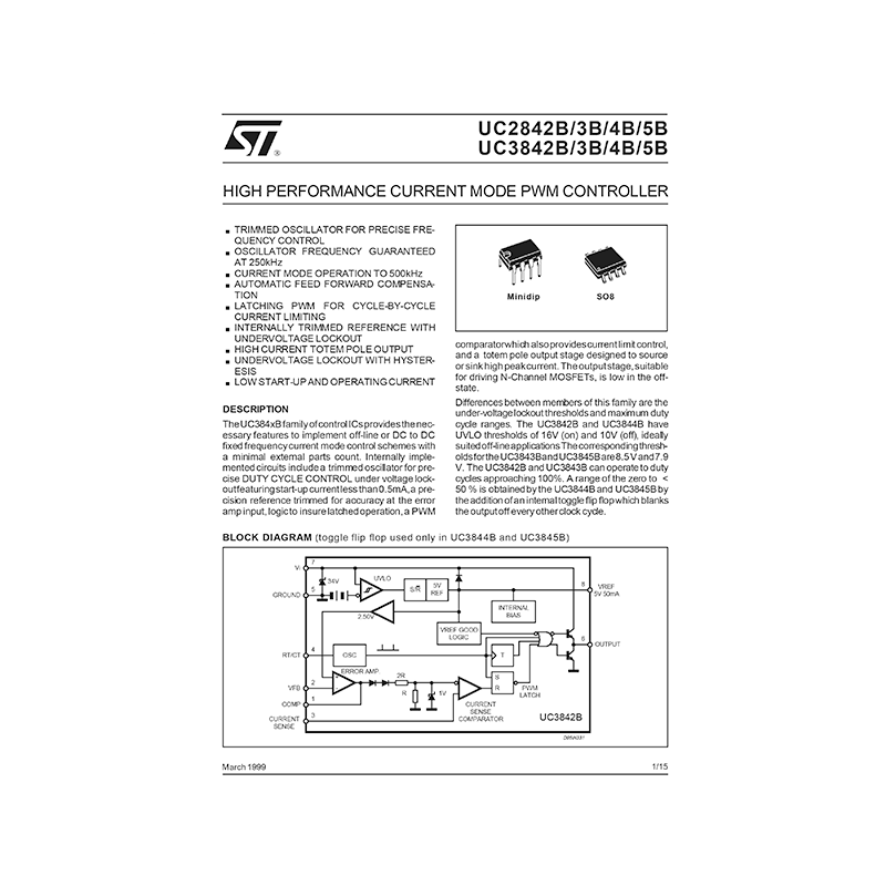
STMicroelectronics UC3843B High Performance Current Mode PWM Controller
* Trimmed Oscillator For Precise Frequency Control
* Oscillator Frequency Guaranteed At 250khz
* Current Mode Operation To 500khz
* Automatic Feed Forward Compensation
* Latching Pwm For Cycle-By-Cycle Current Limiting
* Internally Trimmed Reference With Undervoltage Lockout
* High Current Totem Pole Output
* Undervoltage Lockout With Hysteresis
* Lowstart-Up And Operating Current
The UC384xB family of control ICs provides the necessary features to implement off-line or DC to DC fixed frequency current mode control schemes with a minimal external parts count. Internally implemented circuits include a trimmed oscillator for precise DUTY CYCLE CONTROL under voltage lockout featuring start-up current less than 0.5mA, a precision reference trimmed for accuracy at the error amp input, logic to insure latched operation, a PWM comparator which also provides current limit control, and a totem pole output stage designed to source or sink high peak current.The output stage, suitable for driving N-Channel MOSFETs, is low in the offstate.
Differences between members of this family are the under-voltage lockout thresholds and maximum duty cycle ranges.
Document(s) available
(PDF) DATASHEET
Available languages
ENGLISH (EN)
SUMMARY OF CONTENTS
BLOCK DIAGRAM
ABSOLUTE MAXIMUM RATINGS
PIN CONNECTION (PINOUT)
PIN FUNCTIONS
ORDERING NUMBERS
THERMAL DATA
ELECTRICAL CHARACTERISTICS
– REFERENCE SECTION
– OSCILLATOR SECTION
– ERROR AMP SECTION
– CURRENT SENSE SECTION
– OUTPUT SECTION
– UNDER-VOLTAGE LOCKOUT SECTION
– PWM SECTION
– TOTAL STANDBY CURRENT
Figure 1: Open Loop Test Circuit.
Figure 2: Timing Resistor vs. Oscillator Frequency
Figure 3: Output Dead-Time vs. Oscillator Frequency
Figure 4: Oscillator Discharge Current vs. Temperature.
Figure 5: Maximum Output Duty Cycle vs. Timing Resistor.
Figure 6: Error Amp Open-Loop Gain and Phase vs. Frequency.
Figure 7: Current Sense Input Threshold vs. Error Amp Output Voltage.
Figure 8: Reference Voltage Change vs. Source Current.
Figure 9: Reference Short Circuit Current vs. Temperature.
Figure 10: Output Saturation Voltagevs. Load Current.
Figure 11: Supply Current vs. Supply Voltage.
Figure 12: Output Waveform.
Figure 13: Output Cross Conduction.
Figure 14: Oscillator and Output Waveforms.
Figure 15: ErrorAmp Configuration.
Figure 16: Under Voltage Lockout.
Figure 17: Current Sense Circuit.
Figure 18: SlopeCompensation Techniques.
Figure 19: IsolatedMOSFET Drive and Current Transformer Sensing.
Figure 20: Latched Shutdown.
Figure 21: Error Amplifier Compensation.
Figure 22: External Clock Synchronization.
Figure 23: External Duty Cycle Clamp and Multi Unit Synchronization.
Figure 24: Soft-Start Circuit.
Figure 25: Soft-Start and Error Amplifier Output Duty Cycle Clamp.
OUTLINE AND MECHANICAL DATA
Why download the Datasheet?
This datasheet provides all the information from ST about the UC3843B PWM controller, as detailed in the table of contents. Reading it completely will address most questions you might have. You can download and save it for offline use, including viewing it on your device or printing it for your convenience if you prefer a paper version.
How to download the Datasheet?
Download it by clicking the button below
Helped you out?
Glad to hear that. It would be awesome if you could . . .


