TDA2003 ST 10W Car Radio Audio Amplifier Data Sheet
Download PDF datasheet for SGS-Thomson Microelectronics ST TDA2003 10W Car Radio Audio Amplifier Linear Integrated Circuit (EN) 11 pages 1995 zip
Description
This PDF data sheet is for the SGS-Thomson TDA2003 audio amplifier.
About the Item
SGS-THOMSON Microelectronics ST TDA2003 10W Car Radio Audio Amplifier Linear Integrated Circuit
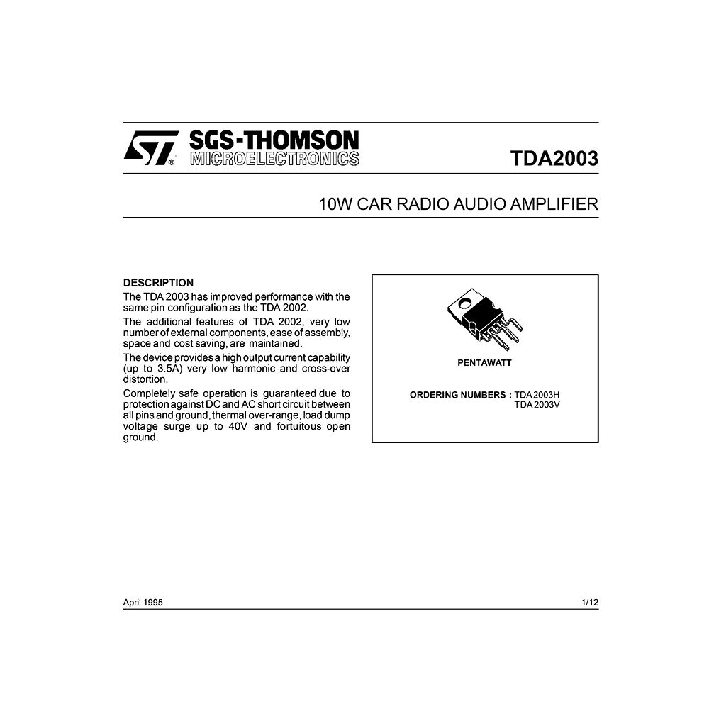
The TDA 2003 has improved performance with the same pin configuration as the TDA 2002.
The additional features of TDA 2002, very low numberof external components,ease of assembly, space and cost saving, are maintained.
The device providesa high output current capability (up to 3.5A) very low harmonic and cross-over distortion.
Completely safe operation is guaranteed due to protectionagainstDCand ACshort circuit between all pins and ground,thermal over-range, load dump voltage surge up to 40V and fortuitous open ground.
(PDF) DATASHEET (ENGLISH)
SUMMARY OF CONTENTS
– Absolute Maximum Ratings: Peak supply voltage, DC supply voltage, Operating supply voltage, Output peak current, Power dissipation, Storage and junction temperature.
– Test Circuit
– Pin Connection. TDA2003 pinout.
– Schematic Diagram
– Thermal Data
– DC Test Circuit
– AC Test Circuit
– Electrical Characteristics
– DC Characteristics
– AC Characteristics
– Electrical Characteristics
– Figure 1. Quiescent output voltage vs. supply voltage
– Figure 2. Quiescent drain current vs. supply voltage
– Figure 3. Output power vs. supply voltage
– Figure 4. Output power vs. load resistance
– Figure 5. Gain vs. input sensivity
– Figure 6. Gain vs. inputvsensivity
– Figure 7. Distortion vs. output power
– Figure 8. Distortion vs. frequency
– Figure 9. Supply voltage rejection vs. voltage gain
– Figure 10. Supply voltage rejection vs. frequency
– Figure 11. Power dissipation and efficiency vs. output power
– Figure 12. Power dissipation and efficiency vs. output power
– Figure 13. Maximum power dissipation vs. supply voltage (sine wave operation)
– Figure 14. Maximumallowable power dissipation vs. ambient temperature
– Figure 15. Typical values of capacitor (CX) for different values of frequency reponse (B)
– Application Information
– Figure 16. Typical application circuit
– Figure 17. P.C. board and component layout for the circuit of fig. 16
– Figure 18. 20W bridge configuration application circuit
– Figure 19. P.C. board and component layout for the circuit of fig. 18
– Figure 20. Low cost bridge configuration application circuit
– Figure 21. P.C. board and component layout for the low-cost bridge amplifier of fig. 20, in stereo version
– Built-In Protection Systems. Load dump voltage surge. Short-circuit (AC and DC conditions). Polarity inversion. Open ground. Inductive load. DC voltage. Thermal shut-down.
Figure 24. Output power and drain current vs. case temperature
Figure 25. Output power and drain current vs. case temperature
– Pratical Consideration. Printed circuit board. Assembly suggestion. Application suggestions.
– PENTAWATT Package Mechanical Data
Why download the Datasheet?
This datasheet provides all the information from SGS-Thomson about the TDA2003 audio amplifier, as detailed in the table of contents. Reading it completely will address most questions you might have. You can download and save it for offline use, including viewing it on your device or printing it for your convenience if you prefer a paper version.
How to download the Datasheet?
Download it by clicking the button below
Helped you out?
Glad to hear that. It would be awesome if you could . . .


