UC3842 Philips Current-mode PWM controller Data Sheet
Download PDF datasheet for Philips Semiconductors UC3842 Current-mode PWM controller (EN) 8 pages 853-0614 13721 1998 zip
Description
This PDF datasheet is for the Philips UC3842 PWM controller.
About the Item
Philips Semiconductors UC3842 Current-mode PWM controller
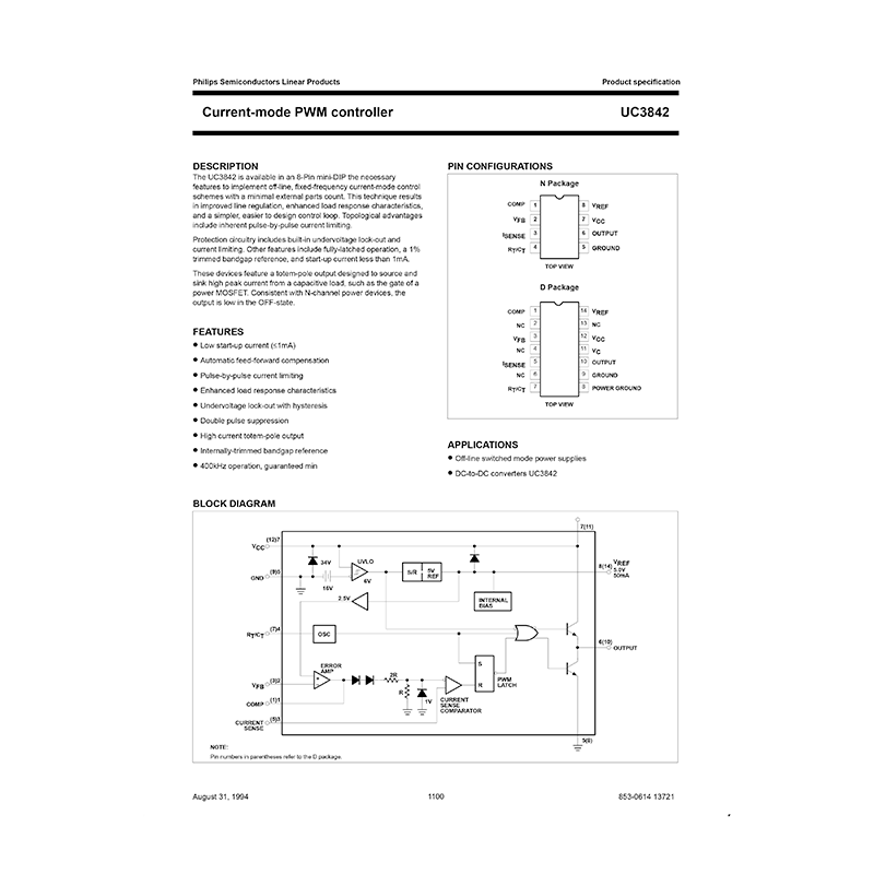
The UC3842 is available in an 8-Pin mini-DIP the necessary features to implement off-line, fixed-frequency current-mode control schemes with a minimal external parts count. This technique results in improved line regulation, enhanced load response characteristics, and a simpler, easier to design control loop. Topological advantages include inherent pulse-by-pulse current limiting.
Protection circuitry includes built-in undervoltage lock-out and current limiting. Other features include fully-latched operation, a 1% trimmed bandgap reference, and start-up current less than 1mA.
These devices feature a totem-pole output designed to source and sink high peak current from a capacitive load, such as the gate of a power MOSFET. Consistent with N-channel power devices, the output is low in the OFF-state.
FEATURES
– Low start-up current
– Automatic feed-forward compensation
– Pulse-by-pulse current limiting
– Enhanced load response characteristics
– Undervoltage lock-out with hysteresis
– Double pulse suppression
– High current totem-pole output
– Internally-trimmed bandgap reference
– 400kHz operation, guaranteed min
Document(s) available
(PDF) DATASHEET
Available languages
ENGLISH (EN)
SUMMARY OF CONTENTS
PIN CONFIGURATIONS (UC3842 PINOUT)
APPLICATIONS
– Off-line switched mode power supplies
– DC-to-DC converters UC3842
BLOCK DIAGRAM
ORDERING INFORMATION
ABSOLUTE MAXIMUM RATINGS
DC AND AC ELECTRICAL CHARACTERISTICS
– Reference section
– Oscillator section
– Error amp section
– Current sense section
– Output section
– Undervoltage lockout section
– PWM section
– Total standby current
– Maximum operating frequency section
UNDERVOLTAGE LOCKOUT
ERROR AMP CONFIGURATION
CURRENT SENSE CIRCUIT
TYPICAL PERFORMANCE CHARACTERISTICS
– Output Saturation Characteristics
– Error Amplifier Open-Loop Frequency Response
OPEN-LOOP LABORATORY TEST FIXTURE
SHUTDOWN TECHNIQUES
OFF-LINE FLYBACK REGULATOR
SPECIFICATIONS
SYNCHRONIZATION AND MAXIMUM DUTY CYCLE CLAMP
Why download the Datasheet?
This datasheet provides all the information from PHILIPS SEMICONDUCTORS about the UC3842 pwm controller, as detailed in the table of contents. Reading it completely will address most questions you might have. You can download and save it for offline use, including viewing it on your device or printing it for your convenience if you prefer a paper version.
How to download the Datasheet?
Download it by clicking the button below
Helped you out?
Glad to hear that. It would be awesome if you could . . .


