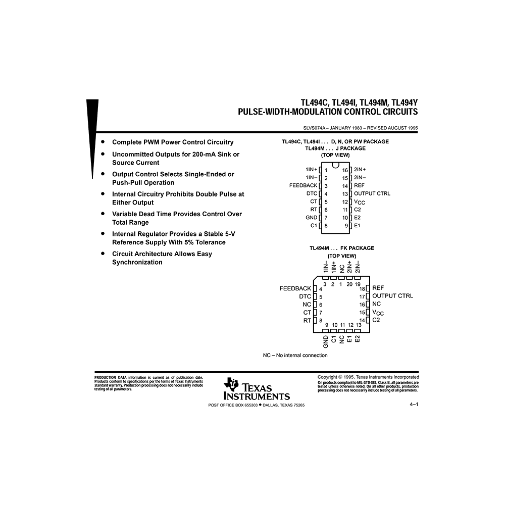
TL494Y Texas Instruments Pulse-Width-Modulation Control Circuit Data Sheet
Download PDF datasheet for Texas Instruments TL494Y Pulse-Width-Modulation Control Circuit (EN) 13 pages SLVS074A 1995 zip
Description
This PDF datasheet is for the Texas Instruments TL494Y PWM controller.
About the Item
Texas Instruments TL494Y Pulse-Width-Modulation Control Circuit
* Complete PWM Power Control Circuitry
* Uncommitted Outputs for 200-mA Sink or Source Current
* Output Control Selects Single-Ended or Push-Pull Operation
* Internal Circuitry Prohibits Double Pulse at Either Output
* Variable Dead Time Provides Control Over Total Range
* Internal Regulator Provides a Stable 5-V Reference Supply With 5% Tolerance
* Circuit Architecture Allows Easy Synchronization
The TL494 incorporates on a single monolithic chip all the functions required in the construction of a pulse-width-modulation control circuit. Designed primarily for power supply control, this device offers the systems engineer the flexibility to tailor the power supply control circuitry to a specific application.
The TL494 contains two error amplifiers, an on-chip adjustable oscillator, a dead-time control (DTC) comparator, a pulse-steering control flip-flop, a 5-V, 5%-precision regulator, and output-control circuits.
The error amplifiers exhibit a common-mode voltage range from -0.3 V to VCC -2 V. The dead-time control comparator has a fixed offset that provides approximately 5% dead time. The on-chip oscillator may be bypassed by terminating RT to the reference output and providing a sawtooth input to CT, or it may drive the common circuits in synchronous multiple-rail power supplies.
The uncommitted output transistors provide either common-emitter or emitter-follower output capability. The TL494 provides for push-pull or single-ended output operation, which may be selected through the outputcontrol function. The architecture of this device prohibits the possibility of either output being pulsed twice during push-pull operation.
(PDF) DATASHEET (ENGLISH)
SUMMARY OF CONTENTS
– Package top view (Pinout)
– Function table
– Functional block diagram
– Chip information
– Absolute maximum ratings
– Dissipation rating table
– Recommended operating conditions
– Electrical characteristics
– Parameter measurement information
– Test circuit
– Figure 1. Operational Test Circuit and Waveforms
– Figure 2. Amplifier Characteristics
– Figure 3. Common-Emitter Configuration
– Figure 4. Emitter-Follower Configuration
– Typical characteristics
Why download the Datasheet?
This datasheet provides all the information from Texas Instruments about the TL494Y PWM controller, as detailed in the table of contents. Reading it completely will address most questions you might have. You can download and save it for offline use, including viewing it on your device or printing it for your convenience if you prefer a paper version.
How to download the Datasheet?
Download it by clicking the button below
Helped you out?
Glad to hear that. It would be awesome if you could . . .


