PIC16F874 Microchip Microcontroller Data Sheet
Download PDF datasheet for Microchip Technology PIC16F874 8-bit CMOS FLASH Microcontroller (EN) 218 pages DS30292C 2001 zip
Description
This PDF datasheet is for the Microchip PIC16F874 microcontroller.
About the Item
Microchip PIC16F874 Microcontroller
This document contains Microchip PIC16F874 specific information. Additional information may be found in the PICmicro Mid-Range Reference Manual (DS33023). The Reference Manual should be considered a complementary document to this data sheet, and is highly recommended reading for a better understanding of the device architecture and operation of the peripheral modules.
Document(s) available
(PDF) DATASHEET
Available languages
ENGLISH (EN)
SUMMARY OF CONTENTS
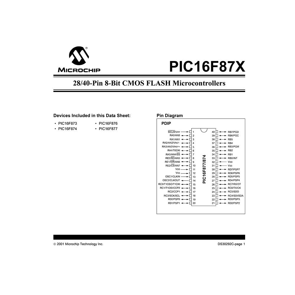
– Pin Diagram
1. Device Overview. Block diagram. Pinout description.
2. Memory Organization. Program memory map and stack. Program Memory Organization. Data Memory Organization. Register file map. PCL and PCLATH. Program Memory Paging. Call of a subroutine. Indirect Addressing, INDF and FSR Registers.
3. I/O Ports. PORTA and the TRISA Register. Initializing port. PORTA functions. Summary of registers associated with PORTA. PORTB and the TRISB Register. PORTB functions. Summary of registers associated with PORTB. PORTC and the TRISC Register. PORTC functions. Summary of registers associated with PORTC. PORTD and the TRISD Register. PORTD functions. Summary of registers associated with PORTD. PORTE and the TRISE Register. PORTE functions. Summary of registers associated with PORTE. Parallel Slave Port.
4. Data EEPROM and FLASH Program Memory. EECON1 and EECON2 Registers. Reading the EEPROM Data Memory. Writing to the EEPROM Data Memory. Reading the FLASH Program Memory. Writing to the FLASH Program Memory. Write Verify. Protection Against Spurious Writes. Operation While Code Protected. FLASH Program Memory Write Protection.
5. Timer0 Module. Timer0 Interrupt. Using Timer0 with an External Clock. Prescaler.
6. Timer1 Module. Timer1 Operation in Timer Mode. Timer1 Counter Operation. Timer1 Operation in Synchronized Counter Mode. Timer1 Operation in Asynchronous Counter Mode. Timer1 Oscillator. Resetting Timer1 using a CCP Trigger Output. Resetting of Timer1 Register Pair (TMR1H, TMR1L). Timer1 Prescaler.
7. Timer2 Module. Timer2 Prescaler and Postscaler. Output of TMR2.
8. Capture/Compare/PWM Modules. Capture Mode. Compare Mode. PWM Mode (PWM).
9. Master Synchronous Serial Port (MSSP) Module. SPI Mode. MSSP I2C Operation. Connection Considerations for I2C Bus.
10. Addressable Universal Synchronous Asynchronous Receiver Transmitter (USART). USART Baud Rate Generator (BRG). USART Asynchronous Mode. USART Synchronous Master Mode. USART Synchronous Slave Mode.
11. Analog-to-Digital Converter (A/D) Module. A/D Acquisition Requirements. Selecting the A/D Conversion Clock. Configuring Analog Port Pins. A/D Conversions. A/D Operation During SLEEP. Effects of a RESET.
12. Special Features of the CPU. Configuration Bits. Oscillator Configurations. RESET. Power-On Reset (POR). Power-up Timer (PWRT). Oscillator Start-up Timer (OST). Brown-out Reset (BOR). Time-out Sequence. Power Control/Status Register (PCON). Interrupts. Context Saving During Interrupts. Watchdog Timer (WDT). Power-down Mode (SLEEP). In-Circuit Debugger. Program Verification/Code Protection. ID Locations. In-Circuit Serial Programming. Low Voltage ICSP Programming.
13. Instruction Set Summary. Instruction Descriptions.
14. Development Support. MPLAB Integrated Development Environment Software. MPASM Assembler. MPLAB C17 and MPLAB C18 C Compilers. MPLINK Object Linker/ MPLIB Object Librarian. MPLAB SIM Software Simulator. MPLAB ICE High Performance Universal In-Circuit Emulator with MPLAB IDE. ICEPIC In-Circuit Emulator. MPLAB ICD In-Circuit Debugger. PRO MATE II Universal Device Programmer. PICSTART Plus Entry Level Development Programmer. PICDEM 1 Low Cost PICmicro Demonstration Board. PICDEM 2 Low Cost PIC16CXX Demonstration Board. PICDEM 3 Low Cost PIC16CXXX Demonstration Board. PICDEM 17 Demonstration Board. KEELOQ Evaluation and Programming Tools.
15. Electrical Characteristics. Absolute Maximum Ratings. DC Characteristics. Timing Parameter Symbology.
16. DC and AC Characteristics Graphs and Tables
17. Packaging Information. Package Marking Information.
Appendix A: Revision History
Appendix B: Device Differences
Appendix C: Conversion Considerations
PIC16F87X Product Identification System
Why Download the Datasheet?
This datasheet provides all the information from MICROCHIP TECHNOLOGY about the PIC16F874 microcontroller, as detailed in the table of contents. Reading it completely will address most questions you might have. You can download and save it for offline use, including viewing it on your device or printing it for your convenience if you prefer a paper version.
How to Download the Datasheet?
Download it by clicking the button below
Helped you out?
Glad to hear that. It would be awesome if you could . . .


