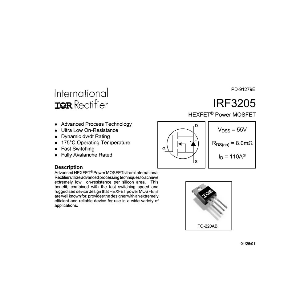
IRF3205 International Rectifier HEXFET Power MOS Field Effect Transistor Data Sheet
Download PDF datasheet for International Rectifier IRF3205 HEXFET Power MOS Transistor (EN) 9 pages PD-91279E 2001 zip
Description
This PDF datasheet is for the International Rectifier IRF3205 HEXFET Power MOS Field Effect Transistor.
About the Item
International Rectifier IRF3205 HEXFET Power MOS Field Effect Transistor
* Advanced Process Technology
* Ultra Low On-Resistance
* Dynamic dv/dt Rating
* 175 deg C Operating Temperature
* Fast Switching
* Fully Avalanche Rated
Advanced HEXFET(R) Power MOSFETs from International Rectifier utilize advanced processing techniques to achieve extremely low on-resistance per silicon area. This benefit, combined with the fast switching speed and ruggedized device design that HEXFET power MOSFETs are well known for, provides the designer with an extremely efficient and reliable device for use in a wide variety of applications.
The TO-220 package is universally preferred for all commercial-industrial applications at power dissipation levels to approximately 50 watts. The low thermal resistance and low package cost of the TO-220 contribute to its wide acceptance throughout the industry.
(PDF) DATASHEET (ENGLISH)
SUMMARY OF CONTENTS
ABSOLUTE MAXIMUM RATINGS
– Continuous Drain Current
– Pulsed Drain Current
– Power Dissipation
– Linear Derating Factor
– Gate-to-Source Voltage
– Avalanche Current
– Repetitive Avalanche Energy
– Peak Diode Recovery dv/dt
– Operating Junction and Storage Temperature Range
– Soldering Temperature
– Mounting torque
THERMAL RESISTANCE
ELECTRICAL CHARACTERISTICS
SOURCE-DRAIN RATINGS AND CHARACTERISTICS
Fig 1. Typical Output Characteristics
Fig 2. Typical Output Characteristics
Fig 3. Typical Transfer Characteristics
Fig 4. Normalized On-Resistance Vs. Temperature
Fig 5. Typical Capacitance Vs. Drain-to-Source Voltage
Fig 6. Typical Gate Charge Vs. Gate-to-Source Voltage
Fig 7. Typical Source-Drain Diode Forward Voltage
Fig 8. Maximum Safe Operating Area
Fig 9. Maximum Drain Current Vs. Case Temperature
Fig 10a. Switching Time Test Circuit
Fig 10b. Switching Time Waveforms
Fig 11. Maximum Effective Transient Thermal Impedance, Junction-to-Case
Fig 12a. Unclamped Inductive Test Circuit
Fig 12b. Unclamped Inductive Waveforms
Fig 12c. Maximum Avalanche Energy Vs. Drain Current
Fig 13a. Basic Gate Charge Waveform
Fig 13b. Gate Charge Test Circuit
PEAK DIODE RECOVERY dv/dt TEST CIRCUIT
Fig 14. For N-Channel HEXFETS
PACKAGE OUTLINE
PART MARKING INFORMATION
Why download the Datasheet?
This datasheet provides all the information from International Rectifier about the IRF3205 transistor, as detailed in the table of contents. Reading it completely will address most questions you might have. You can download and save it for offline use, including viewing it on your device or printing it for your convenience if you prefer a paper version.
How to download the Datasheet?
Download it by clicking the button below
Helped you out?
Glad to hear that. It would be awesome if you could . . .


